
Mounting
Typical Application
“Typical application” of Silverthin™ Slewing Ring Bearings will exhibit the conditions listed below. Special consideration must be given to bearing selection and features whenever the application conditions differ from those considered “typical”.
Those typical application conditions are:
- Vertical axis of rotation. Essentially, the bearing mounted “flat”.
- Compressive thrust and moment loads being predominant compared to tension loading.
- Radial load limited to less than 10% of the thrust load.
- For single row bearings, intermittent rotation (not continuous) should not exceed a pitch-line velocity of 500 feet/minute.
Operating temperature between -40ºF to +140ºF. - Mounting surface geometry and installation procedures to assure roundness and flatness of both races. An example approach would be to apply a centered thrust load while tightening the bolts using the alternating star pattern method.
- Periodic checking of mounting bolts to verify proper tension is provided for.
- Periodic lubrication is provided for.
Load Capability
Silverthin™ Slewing Ring Bearings are designed to accommodate significant radial, thrust and moment loads as shown below:
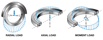
This is accomplished in most cases by the unique four-point contact raceway geometry, which is similar in concept to Silverthin™ X-Type Thin Section bearings. This allows a single bearing to accommodate all three loading scenarios noted above, either individually or a combination thereof.

Mounting
Mounting surfaces need to be machined accurately for proper function of the bearing. Where standard bolt patterns cannot be accommodated, contact Silverthin Engineering for alternative options. Consideration must be given to mounting tension or compression. In tension, BOLT strength becomes the limiting load consideration, the load curve no longer applies, and special considerations must be made. See additional guidelines below.
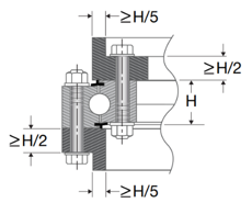
Minimum Mounting Structure Guidelines
Generally, this rule of thumb will provide adequate structural integrity.
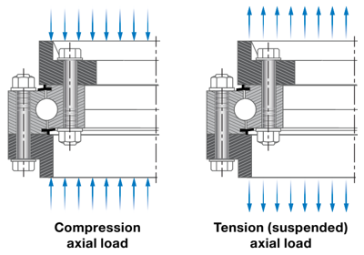
Mounting – Tension versus Compression
As mentioned earlier, it is best to mount the bearings in “compression” as shown below. This ensures that the load is carried by the balls, which is represented in the load curve provided. Tension mounting has significantly less capacity, as then the bolt strength becomes the primary consideration for capacity.
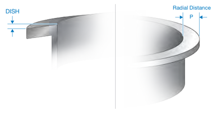
Flatness & Mounting Surface Dish
(Mounting Surface)
Flatness of the bearing mounting surface is critical to optimal performance. Frequently mounting structures are welded or worked in a way to induce stress into the structure. These stresses must be relieved, following which the bearing mounting surface must be machined flat. Flatness must be considered:
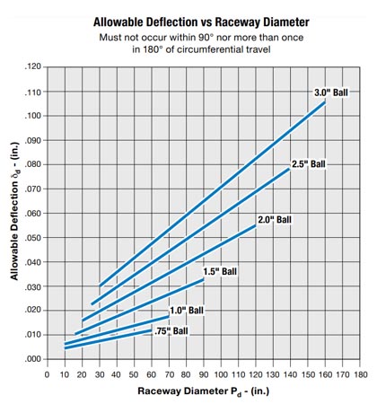
Circumferential Direction (δr): The amount of out-of-flatness allowable in the circumferential direction for four-point ball bearings is shown in the figure below. This amount of out-of-flatness must not be exceeded in a span less than 90°, and not more than once in span not more than 180°.
Allowable Dish or Perpendicularity Deviation in the Radial direction (δp): For four-point contact ball bearing designs, this amount of dish allowable can be approximated using the formula:
δp ≈ 0.001 ∗ Dw ∗ P
Where: P = radial dim of the mounting structure face (in)
Dw = rolling element diameter (in)
Note that if an application requires greater precision or low rotational torque, it may be necessary to reduce the values of δr and δp. For roller bearings, the amount of flatness allowable is approximately 2/3 of that for an equivalent sized four-point contact ball bearing.
Bolts
It is always suggested that bolts be selected with the advice and assistance of a fastening hardware supplier. Bolt quality, pretensioning procedures, and maintenance can vary widely.
The optimal bolting arrangement has a bolt circle in both the inner and outer races with equally spaced fasteners. This results in a more uniform mounting arrangement, yielding the best performance between the bearing and the fasteners. This is not always possible due to mounting structure arrangements, and holes may be shifted accordingly. In these cases, testing is recommended to determine actual bolt loads, validate joint configuration and assembly procedure.
As a starting point to determine the approximate load on the heaviest loaded bolt, the following formula can be used. Please note that Silverthin™ makes no warranty, expressed or implied, regarding bolt adequacy. It is strongly recommended that testing be performed to determine the actual load, as this is the only reliable way to be certain.
RB=(12 ×M ×r)/(BC ×n)±F_a/n
Where:
RB=Total load on heaviest loaded bolt (lbs)
M=Moment load (ft-lbs)
R=Rigidity facor. Use 3 for bearings and support structures of average stiffness
Fa=Axial load (lbs)
If Fa is in tension use +
If Fa is in compression use –
Refer to section “Mounting – Tension versus Compression”
BC=Bolt circle diameter (in)
N=Total number of eqully distributed bolts
SF=Bolt factor of Safety. Minimum recommended value= 3. See formula below:
SF=(Bolt Proof Load Rating)/RB
| Bolt Diameter (INCH) |
Proof Load (LBS) |
|---|---|
| 1/2 | 17,000 |
| 5/8 | 27,100 |
| 3/4 | 40,100 |
| 7/8 | 55,400 |
| 1 | 72,700 |
| 1 1/8 | 91,600 |
| 1 1/4 | 116,300 |
| 1 1/2 | 168,600 |
Other Bolting Recommendations:
- Use hexagon head high strength bolts with coarse threads according to SAE J429, Grade 8 or ASTM A490/A490M or ISO 898-1, Grade 10.9 tensioned to 70% of their yield strength.
- Use hexagon head coarse thread nuts where applicable according to SAE J995, Grade 8 or ASTM A563, Grade DH or ISO 898-2, Class 10.
- For optimal bolt tension, the ratio of the distance from the bottom of the bolt head to the first thread of engagement should be 3.5 or greater. Testing is required for validation.
- All mounting bolts in each ring should have equal clamp length.
- The distance between the head of the bolt and the bolt threads should be at least equal to the bolt body diameter.
- The length of the thread engagement of the bolt in the mating steel structure should be at least 1.25 times the bolt diameter.
- Bench tests are recommended to validate that the bolt tensioning method achieves desired results prior to equipment testing.
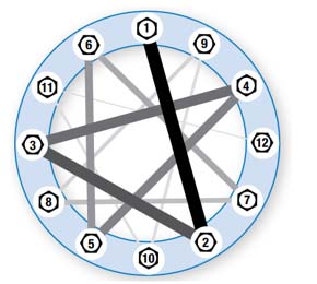
Install the washers, nuts and bolts in the bearing and supporting structure and hand tighten. Do not distort the bearing to install bolts. Apply a moderate centered thrust load to the bearing. Tighten the bolts to the equipment designer’s specifications. A common approach is to use a star pattern to tighten the bolts, sequences as shown in the diagram below. The pattern is usually done in 3 steps at approximately 30%, 80% and 100% of the final bolt torque or tension level specified by the equipment designer.
Loss of proper tension can lead to premature bolt failure, failure of the bearing and structure, damage to components, and fatality or injury to anyone in the vicinity. The bolts require frequent inspection for proper tension, which is commonly accomplished by measuring torque of the bolt.
Securing Bearing to the Mounting Surface
When installing the bearing, it is important to ensure that the bearing is as round as possible. This will optimize load distribution and promote the smoothest operation. The following procedures are recommended as an aid.
Use hardened round flat steel washers in accordance with ASTM F436 under the head of the bolt, and the nut. Lock washers, and locking compounds on the thread, are not recommended.