
Mounting & Installation
Inspection, Mating Component Design and Installation
Silverthin Thin Section bearings are unique for many reasons, and their usage considerations are stricter than standard heavier section bearings. The bearings are designed to save space and weight, and have thinner rings, smaller balls and a greater ball complement compared to bearings of similar diameter. Thin section bearings will be more sensitive to the geometry of mating components as their shape is greatly impacted by their thin design. These bearings will also tend to conform to their mating components, as such it is important that attention is paid to both roundness and flatness of the shaft and housing.
Inspection
Due to the flexibility of thin section bearings, traditional measuring techniques will not yield accurate results. For example, bearing inner and outer diameters cannot be measured with calipers, micrometers or other 2-point measuring methods. In a free state the bearing rings are not perfectly round and must be measured at multiple locations with the values averaged to determine a diameter. Instead, a CMM, air gage, or other multiple position measuring method is required.
This is also true of bearing runout. Runout for Silverthin Thin Section bearings is the deviation of the measurement between the ball path and the inner or outer diameter of the bearing. ABMA 26.2 defines runout of thin section bearings as the raceway to bore or outer diameter thickness variation (radial runout) or the raceway to face parallelism (axial runout).
Mating Component Design
Tolerancing of the shaft and housing features are critical for optimal performance of Silverthin Thin Section bearings. This is because the thin nature of the bearing rings will tend to conform to those features. The following recommendations, or better, should be applied to the design:
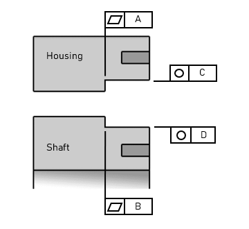
Flatness Tolerance of the bearing seat that contacts the bearing face should not exceed the bearings Axial Runout specification.
- Flatness ▱ A for the outer ring housing/outer ring bearing face interface
- Flatness ▱ B for the inner ring shaft/inner ring bearing face interface
Roundness Tolerance of the bearing seat that contacts the bearing ID or OD should not exceed the bearings Radial Runout specification.
- Roundness ◯ C for the outer ring housing ID
- Roundness ◯ D for the inner ring shaft ID
Installation
For interference fits heating and cooling should be used as appropriate to install the bearings onto shafts and into housings. Note that all components should be at room temperature before tightening clamps. If a heating and cooling process is impractical due to the assembly process, bearings may be pressed into the assembly. Press force should only be applied through the bearing ring that is being installed. Installing a bearing inner ring onto a shaft requires pressing bearing inner ring face onto the shaft and installing the bearing outer ring into housing requires pressing bearing outer ring face into the housing.
Clamping of the bearings into place is recommended. Relying solely on a press fit to secure the bearings is insufficient. There should be positive clamping where the face of the ring being clamped protrudes slightly above the clamping face. For even clamping force many fasteners should be used and tightened in a star pattern.
Shaft and Housing Fit Recommendations
In the tolerance tables, as well as on the datasheets produced using the Silverthin Datasheet Generator, there are ‘standard’ recommendations for shaft and housing tolerances which vary depending on bearing type and rotating conditions. Note that these are suggestions, but not firm rules.
There are many factors that often must be considered when selecting appropriate shaft and housing fits, including:
- Assembly method
- Is a slip fit preferred?
- Disassembly requirements
- Does the assembly need to be taken apart for future use?
- Bearing torque
- How will the fits impact bearing torque based on changes to preload or clearance when mounting and during operation?
- Clamping method
- Is the clamping sufficient to prevent fretting on the shaft or in the housing?
- Overall positioning and rotational accuracy